
 admin
Flexible PCBs Bend and Twist
Whether or not your PCB can bend and twist depends on the design, materials, and thickness of the circuit board. The flex circuit stackup can also influence bending performance. For example, the layer stackup used on rigid-flex boards differs from that of traditional PCBs and must be optimized to withstand frequent bending and dynamic flexing. In general, a flexible circuit can only be bent a certain number of times before it begins to show signs of fatigue and damage.
To make a flex circuit board, copper foil is deposited as a thin layer over dielectric and then etched. A variety of metals can be used for the conductive path, but copper is the most popular due to its low cost and superior electrical properties. The conductive path is typically separated from the dielectric by an adhesive. While there are many different types of adhesives, polyimide is the most common choice for flex circuits because it’s durable and flexible. It can also withstand high temperatures and solder reflow cycles.
A flex circuit can have single- or double-sided conductor layers and is either bare or plated. It can also have plated through holes. The design of a flex circuit boards determines the type of manufacturing process it will require. For instance, a bare flex is usually fabricated through etching and photolithography while a plated flex can be through-hole or surface-mount technology (SMT).
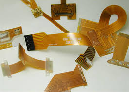
Can Flexible PCBs Bend and Twist?
The minimum angle at which a flex circuit can bend is known as the flex radius. This value must be determined early in the design phase to ensure that your flex circuit can sustain the required amount of bending without damaging the copper. It’s a good idea to use gradual and large curved angles rather than sharp ones for optimum flexibility. You should also avoid placing components and plated through-holes within the flex radius. Conductors should be positioned perpendicular to the neutral bend axis and should be staggered on multi-layered flex circuits.
When designing a flex circuit, you should take into account the types of coverlays, flexible solder masks, stiffeners, and adhesives used. The selection of these components will have a big impact on the strength and durability of your flex circuit.
You should also pay attention to the type of copper used. Avoid ED copper, which is a plated process, and opt for roll annealed copper instead. It’s also important to call out the copper grain direction on the fabrication drawing. It’s best to use teardrop (pad fillets) shaped vias when connecting traces to reduce stress concentration spots. In addition, you should use large annular rings when possible to minimize stress in the connection area.
Lastly, it’s important to keep in mind that a flex circuit will be more difficult to manufacture and reliably produce if you incorporate too many tight features. Keeping key components such as vias, pads, and plated through-holes away from the flex circuit’s bending region will help it endure repeated flexing. You should also consider the amount of copper that’s used and the thickness of the substrate.
